
Suppressing Side Channels in an Untrusted Data Center via Retrofitted Defenses
Summary
In the future, the world might want international agreements to govern AI development. Such agreements are likely to include provisions about what AI chips can and cannot be used for (e.g. no undeclared models are in deployment), and verification mechanisms to ensure every side is following the rules. One proposed method for this chip use verification is network taps. These are devices that intercept traffic between the AI accelerators and any of their users, or traffic between servers, to help detect malicious data transfer. For network taps to be effective, they must intercept all or almost all communication with the AI accelerators.
I surveyed the literature on side-channels and possible mitigations to find out if—under the scenario named above—air-gapping can be made secure enough that evasion would likely be caught. Note that the threat model here is different from air-gapping in cybersecurity, where the goal is to prevent secrets from being leaked. While cybersecurity is an offense-dominant problem (the attacker needs to succeed only once), verification is the reverse (the attacker loses if caught even once). This is one reason why I think that preventing bypassing of network monitoring is more viable than one would intuitively think, given how hard the cybersecurity version of the problem is. Another reason is that side-channel suppression can make the expected reward of a cheating attempt not worth the detection risk, while still not being perfectly impenetrable everywhere:
Tolerating single-digit kilobits per second of physically possible2 covert bandwidth substantially reduces the cost and complexity of the defenses needed. With this requirement, my expectation (based on a three-week research sprint) is that defense-dominance is achievable in guarded facilities (personnel, cameras, fences etc.). However, note that this work is the result of a two-week research sprint and far from conclusive. Consider this analysis as an investigation of the first principles and a first-pass viability study.
I present an example of a defense architecture towards the end of this post. It leverages a synergy of cheap enclosures, sensors, jamming, unannounced hardware inspections and physical security to achieve defense-dominance at an estimated (!) Bill-of-Materials (BOM) below 1% of the cost of the monitored cluster (this is assuming economies of scale, and that cheaply welded sheet metal enclosures can attenuate RF signal effectively).
Intro
A promising idea for how to verify claims about the usage of AI-specialized hardware has emerged recently: Rather than attempting to create custom AI accelerators trusted even by mutually distrusting adversaries, one can target the communication links in and out of such hardware.
In principle, this enables a retrofittable architecture that can make many concrete claims about the usage of that AI verifiable, even if the hardware is untrusted (the network taps need to be trusted/monitored, however, which I expect to be a tractable problem). The intercepted traffic could either be within a datacenter (i.e. one server rack transferring model activations to another), or between the hardware and any users outside the datacenter.
Both kinds of traffic are rich in information that could prove claims such as the following (to an automated process preserving confidentiality, or a trusted third party):
- Only whitelisted models are deployed in inference
- No unreported training runs are happening in the datacenter, including asynchronous training within single servers/racks/pods
- The whitelisted models are not used for blacklisted purposes (e.g. such as domestic mass surveillance or developing unsafe AI)
- Evaluations are performed on the claimed model, not a decoy
Among other possible, governance-relevant claims.
The viability of such a verification setup (network taps + automated data analysis and compliance-check) critically depends on the network taps not being bypassed: Even if all optical fiber cables out of a cluster are tapped, data could plausibly be smuggled around them.
This is the challenge that this post addresses, with the goal of de-risking this verification approach specifically for the toughest case: Nation-state actors exploiting any physically available information channel they can, going as far as hiding hardware inside servers in a way they would expect even a trained inspector to not find.
This may seem a lost cause at first, given the extreme cyber offensive capabilities of advanced nation states, but there are reasons why I currently think this is tractable:
- Tolerate low leakage rates. A non-maximalist requirement on air-gaps can make the required defenses vastly cheaper and quickly scalable. Low-kbps bandwidths are useless for data-parallel synchronous training, and borderline useless for covert distributed inference especially if stacked with other defenses such as periodic memory wipes. Exfiltrating/infiltrating the raw weights of a 70B parameter model (FP8) at 5kbps bandwidth takes over three years.
- Securing against covert adversaries can be significantly more efficient than securing against fully malicious, overt adversaries, since the defender can keep adding detection layers against an adversary who needs to stay covert. This is in contrast to the offense-dominant threat model of traditional cybersecurity, where a secret is to be guarded3 against an adversary and the defender fails (or risks failure) if they make a mistake once. With multi-layered defenses, our verification scenario is defense-dominant in the sense that the adversary fails if they are caught even once, while the defensive layers can synergize into a detection/denial system stronger than the sum of its parts. Furthermore, the defender can leverage psychological deterrence. Example: “Our sensors have a sensitivity of more than 50dB, but we won’t tell you how much more”.
- Information bandwidth is limited by physics and information theory. While physics itself can be relied on, every retrofitted defense leveraging it (such as enclosures or jammers) must of course be monitored and inspected against tampering.
I can hardly make assumptions about the cyber-offensive capabilities of the most advanced attackers in the world4, other than that they are bound by the laws of physics. For creating robust side-channel defenses, minimal other assumptions should be made anyway.
In short, I think that none of the required defenses are blocked by the manufacturing cost of the components needed to achieve an upper bound on possible information bandwidth (around kilobits per second) in and out of server racks or pods, besides the monitored optical communication links. I explain this conclusion of my research further below, but we start with the fundamentals:
The Shannon–Hartley Theorem
An attacker’s covert information rate is fundamentally constrained by two variables: The frequency of their signal and the signal-to-noise ratio (SNR).
Wikipedia:
In information theory, the Shannon–Hartley theorem tells the maximum rate C, at which information can be transmitted over a communications channel of a specified bandwidth B in the presence of noise. The simplified form (frequency-independent SNR) looks as follows5:
C = B * log₂(1 + SNR)
- B dictates how fast one can send independent pulses, i.e. it is the available frequency band used for communication.
- SNR dictates how many different distinct amplitude levels you can accurately distinguish in one pulse before the noise blurs them together, i.e. it is the signal-to-noise ratio.
- log₂ converts those distinct levels into binary bits.
We measure relative amplitudes in decibels (dB), for example when comparing signal-to-noise. Absolute power is often measured relative to 1 milliwatt (dBm).
Side-channel survey
From the defender’s perspective, the objective is suppressing C for all physically possible transmission channels. The number of such independent channels is finite and can be covered comprehensively. I know this is a strong claim, so I appreciate adversarial feedback for the list below:
- Electromagnetic.
- Through air, this includes (almost) the whole electromagnetic spectrum, including light. The lowest frequencies can penetrate even Faraday cages, but their information bandwidth is constrained by their frequency (see above). At DRAM-clock frequencies (GHz), “BitJabber” demonstrated 300,000bps at point-blank range and 100,000bps through a 15cm concrete wall, using only commodity DRAM.
- Through solids, the most significant medium is arguably optical fiber. Such fiber has sub-millimeter thickness and can be hidden inside practically any solid object if the defender does not take this option into account in their defense. Covert channels through tapped fiber links are in-scope as well, when assuming malicious hardware: Additional wavelengths the defender’s sensor does not capture, or modulating timing, polarization etc. Distributed Acoustic Sensing uses optical fiber as vibration/strain sensors over kilometer ranges. Commercial DAS interrogators like the Silixa iDAS reach 50kHz acoustic bandwidth out of the box. A SNR ~25dB can be inferred from Zhang et al. (2026) for an airborne sound source at 2m, but sensors directly contacting fiber would bypass the ~30dB of airborne propagation loss in their setup. For these reasons, we expect Mbps to be possible with optimized hardware.
- Sound waves in air. Purpose-built ultrasonic transducers achieve 800kb/s at 0.7m and 180 kb/s at 6 m (Jiang & Wright, 2017), using OFDM modulation in the 55-400kHz band. The same group achieved 100kb/s at 2.5m (Jiang & Wright, 2016).
- Sound waves in solids. Server racks touching each other, and the ground, may contain hidden devices transmitting signal via vibration in metal and concrete. Lawry et al. (2013) achieved 17.37Mbps through 63.5mm steel using OFDM. Zhang et al. (2024) achieved 2Mbps through 50mm aluminum using deep-learning echo cancellation. Pereira et al. (2023) achieved 19.2kbps through a more complex channel (two 5mm steel plates separated by a 100mm fluid layer). All use piezoelectric transducers with coupling gel on clean, flat surfaces.
- Sound waves in cooling water. Water-filled pipes can act as excellent acoustic waveguides. Shannon capacity at these distances is far above hundreds-of-bps, but strong case studies are few. A related study demonstrated 4Mbps through a steel-water-steel multilayer (radially, not axially) using OFDM (Chakraborty et al., cited in Fishta et al., 2023).
- Conducted signal in power lines. This is a well-established communication path, available even as a household appliance (power line modems). Multiple Mbps are a strict lower limit for possible bandwidth. Without any such malicious hardware, Guri et al. achieved 1kbps by modulating CPU power consumption via a software-only attack.
- Conducted signal in cooling water. Voltage signals travel nearly loss-free in a water column, even if the electric resistance is high. A high-impedance receiver can extract hundreds of kbps or more even through high-purity water (estimate, based on Shannon capacity at thermal noise floor6)
- Physical access. Unauthorized direct access to the monitored hardware obviously breaches the defense. A flash drive smuggled in and out, a bug planted in an enclosure etc.
Some information channels are physically viable, but inherently bandwidth-constrained and are therefore not addressed by the defenses discussed in this post. In fact, this contributes to the argument that upper-bounding covert bandwidth is far cheaper and viable at scale than preventing all information leakage. Magnetic7, thermal, radioactive, and gravitational wave channels are limited by their frequency –and therefore channel rate– as dictated by the Shannon-Hartley theorem.
Making side-channel suppression defense-dominant
Defense-dominance is achieved when the risk-reward calculation for the adversary is negative: The expected reward of successfully evading the defenses (in this setup, orchestrating and obtaining results from secret ML workloads), must be (far) outweighed by the risk –and expected cost– of being caught.
I think that this is achievable in our specific scenario, at reasonable cost, by combining multiple layers of defense in a way that these layers reinforce each other.
- Firstly, the defense setup itself needs protection against tampering, and this applies to all physical barriers, monitors and controls that are relied on. In practice, this means physical monitoring and/or guarding of the facility, no unmonitored access, and unannounced inspections, possibly by teams of multi-organizational members keeping watch on each other. Multinational guards, tamper-evident cameras, secure perimeters, motion sensors etc. Additionally, all verifier-supplied components can be designed with tamper-evidence in mind.
- Second, the physical channels can be blocked via four layers of defense:
- Inspections can reveal hidden hardware that has no legitimate reasons for being present, such as ultrasonic transducers, jamming-resistant antennae or hidden optical fiber.
- The covert signal can be attenuated via filters, buffers, physical interruptions and enclosures. This lowers the SNR on the signal front.
- The noise floor can be set by the verifier, i.e. via jamming. This lowers the SNR on the noise front. Importantly, the verifier produces noise in a way the attacker can not predict and cancel out.
- The verifier installs sensors8 listening for signals that should not be present. This also lowers the SNR on the signal front by forcing the attacker to hide in noise. The jamming noise does not necessarily provide additional cover for the attacker: Sensors can directly synergize with jamming, as the defender controls both devices. Through this synergy, the SNR of the attacker can be forced orders of magnitude below 1.
- “Look-Through” is an established term in the NATO electronic warfare lexicon9, referring to the practice of deactivating the jammer to give the sensor a silence window, possibly even with tight latencies making it physically impossible for an attacker to react in time, before their wavefronts are on their way to the sensor. I coin the term “Interrupted Look Through” (ILT) to distinguish it from
- Continuous Look Through (CLT). The jammer runs uninterrupted, but the sensor receives the waveform or its generation seeds to cancel out the noise. This has been demonstrated in commodity radios at 39dB suppression, not even customizing hardware for this purpose.
The attacker’s signal power would then be far below the noise level (i.e. SNR << 1), leading to channel capacity C << B by the Shannon-Hartley theorem. Where a is the attenuation factor and Pcovert signal is the signal power achievable while remaining undetected by inspections and sensors, we have:
Psignal ≤ Pcovert signal·a.
Pnoise ≥ Pjamming.
⇒ SNR ≤ Pcovert signal·a / Pjamming.
⇒ C ≤ B · log2(1 + Pcovert signal·a / Pjamming).
Thus, to upper-bound the channel capacity at 1% of the bandwidth (i.e. to achieve C ≤ 0.01B), it would suffice to have Pcovert signal·a / Pjamming ≤ 20.01 -1 = -22dB. And to upper-bound the capacity of a 1GHz bandwidth to 1 kb/s (i.e. to achieve C ≤ 0.000001B), it would suffice to have Pcovert signal·a / Pjamming ≤ 20.000001 -1 = - 62dB. For reference, testing indicates that some existing enclosures designed to meet NSA 94-106, an NSA specification for side-channel security, already achieve -100dB of attenuation for at least electromagnetic frequencies of 100MHz to 10GHz.10
Perimeters
This section considers what perimeters would need to be subject to defenses.
AI datacenter hardware is hierarchical: individual accelerators comprise nodes, nodes gather in racks, racks assemble into so-called pods or “Scalable Units” (SU, NVIDIA terminology). Some vendors even consider assemblies of pods/SUs as “SuperPODs”.
The verifier has two kinds of communication to monitor: 1) The prover/outside world communicating with the cluster, and 2) the cluster communicating internally.
- The first type directly informs the largest security perimeter: The datacenter itself. Ideally, no information is to enter or leave through anything other than the monitored fiber links at the datacenter edge.
- The facility can be divided into sub-perimeters, with the goal of preventing any un-monitored communication within, or at least any communication linking to AI accelerators. Due to the hierarchical nature of AI clusters, the verifier must choose how fine-grained these perimeters should be: Individual racks? Pods? SuperPODs? This choice is informed by the workloads to monitor:
For inference, pods are reasonably the largest individual units needed11. Bandwidth in-and-out can be surprisingly low: Apart from occasional file transfers, customer service even at thousands of tokens per second per GPU requires only single-digit Gbps and can be monitored cheaply on the so-called in-band fabric, with no other optical fiber links linking a pod to the rest of the datacenter. However, hardware utilization is typically optimized by high-bandwidth communication (of KV caches) between pods using specialized hardware for prefill and decode stages, making the smallest computing unit a pipeline of two pods12. This could be sized down though, since both such pods would usually contain multiple prefill and decode units each.
Training can require extremely high-bandwidth between pods for gradient all-reduce and model checkpoint storage, but an attacker can exploit far lower covert bandwidth at moderate cost to model performance per FLOP.
The finer-grained the perimeters, the smaller the compute units that can communicate unconstrained and unmonitored internally. The drawback is the cost-difference between e.g. per-pod perimeters and per-rack perimeters.
Visual inspections, disassembly and destructive teardowns
If a randomly sampled batch of devices (sample size n) is checked and every check finds a flaw if there is one, the random sample can upper-bound the total fraction of flawed devices (p) with a certain probability P(detect ≥ 1)
P(detect ≥ 1) = 1 − (1 − p)n

There are levels of inspection, each one with their own tradeoff between thoroughness and invasiveness.
A superficial inspection is the least invasive, visually or with dedicated measuring devices. It can catch blatant violations, such as leakage in RF enclosures. The inspector turns on a jammer inside and measures the leakage from the outside. All verifier-supplied components can be designed to be easily inspectable. For instance, a power filter's or CLT device’s electronics could be embedded in transparent epoxy resin, filled with reflective particles whose exact distribution is known to the auditing body.13
At this shallow level, a majority of a datacenter’s pods could be checked.
Opening or disassembling a server inevitably introduces downtime, but can catch devices hidden inside. The most egregious supply chain attacks can bury malicious hardware deep in superficially unsuspicious hardware, but any commodity hardware beyond agreed specs can be caught this way. Example: Hard drives the attacker did not declare, which may be used to evade scheduled memory wipes.
X-rays can spot deviations from official design spec. Comparing component internals against a known-good reference is already established practice in counterfeit electronic parts detection (SAE AS6171), and is mandated for AI security contexts by the SL5 Standard (controls SR-10 and SR-5(2): "radiographic examination, material analysis, and electrical testing"), following NIST SP 800-161 Rev. 1 supply chain risk management guidance.
Destructive teardowns could deter even egregious supply chain attacks in the best hiding spots.
I am not sure, however, whether this is defense-dominant or offense-dominant. I can only state my intuition that a fully destructive teardown by a capable inspection agency would go a long way towards changing the risk-reward calculation for the attacker. If the inspecting body is allowed to take hardware with them, they have practically unlimited time to find anything suspicious.
Destructive analysis can be selective. Some components are cheaper to replace than others, while being the most critical potential hiding spots.
I can not give confident recommendations here, only my intuition that intelligence services would know what to look for in inspections, or whether any deviation from an official design spec14 could be hidden from them. Off-site inspections do however have an element of psychological deterrence, as the attacker must make unfalsifiable assumptions about what the inspector would miss.
Example Defense Setup (Retrofittable)
The example defense setup below draws perimeters around 8-rack NVIDIA Blackwell SUs15, but aims many of its defenses against both inter-rack and inter-SU side-channels.
Against EM signals
In short, one can combine the following layers of defense:
- A cheap, anti-RF sheet metal enclosure16 around the pod, with at least five faces covered (potentially the floor as well, but metal sheets under racks may be sufficient, given the other defenses listed here). Any openings for cables, cooling water and air flow are guided through conduits with at least two right angles. The enclosure needs doors for maintenance access.
- A directional jammer (or multiple) covering all frequency ranges of interest, aimed at individual racks. It can be orders of magnitude more powerful than any unsuspicious noise floor that server racks usually emit (DDR clock cycles, current on PCBs), while still being harmless to any electronics inside. The enclosure around the pod adds the convenient property of shielding the outside from this jammer.17
- Sheet metal between racks, blocking powerful, short range signaling.
- Placed behind the jammer, with added shielding (e.g. a small metal plate in-between), an RF antenna is aimed at the pod. In addition to this passive shielding, CLT and/or ILT can put further pressure on the attacker.
- Visual inspection, or even destructive teardowns aim to find antennae powerful or sensitive enough to exploit any remaining gaps in the defenses listed above.
Against conducted signals
Let us consider all conductors that can carry electrical signal across racks, or out of the enclosure:
- Power cables
- Metal pipes for cooling water
- The cooling water/liquid itself
- Metal walls of server racks
- The Faraday cage walls
The last two are trivially solved by breaking conductive contact between racks and enclosures. Metal pipes and the cooling water inside can be grounded to the enclosure walls, ideally not right next to each other.
Combating all physically possible communication in power cables, while still keeping insertion losses at a minimum, is more challenging: Low-pass filters for the required currents and voltages are readily available on the market, but they inevitably have a frequency passband up until at least one order of magnitude over the power line’s frequency (~60Hz), otherwise they will introduce significant power loss. Additionally, crude LC filters leak low amplitudes of high-frequency signals as well.
Technically, this is a solved problem for the stop-band: Vendors like Astrodyne TDI, Premier Filters, MPE, and Signal Defense sell filters tested against the NSA’s classified specs (referred to via the “TEMPEST” codename). The components of such devices are not exotic (in fact they are already mass-manufactured), and sceptical readers can convince themselves of this via the readily available technical documentation of such filters.18
This only addresses leakage in the stop-band though, and commercial TEMPEST-grade filters typically leave a passband in the kHz range19 (page 3). Here, CLT is a cheap defense that can push Shannon capacity down to tens of bps per cable. The primary cost drivers of a CLT device would not be the signal generation or processing hardware, but any electronics contacting the high-voltage cable. Both are commodity hardware though, and readily available for cheap.
Against fiber-covert channels
Against the range of possible channels discussed in the side-channel survey above, the defender can use either isolation, deterrence, or both.
An isolation strategy would be to not allow any prover-produced photons to leave the enclosure. This means verifier-controlled Optical-Electrical-Optical (OEO) conversion at the boundary. If the enclosure fully contains a self-sufficient inference unit (including prefill and decode stages), such OEO conversion can be as cheap as a handful of 200G or 400G transceivers for in-band links, while the more expensive compute and storage fabrics can remain unmodified within the perimeter. For the most challenging case, which is pre-training, this would mean hundreds of high-performance transceivers per pod, which would be within single-digit percent cost of the monitored servers.20
Deterrence can either work by inspecting optical hardware for un-specified components or sensitivities, or by not specifying the sensing capabilities of the verifier's passive optical taps. Where OEO conversion is deemed too costly (or constrained by transceiver supply), passive taps can observe multiple optical links with one sensor, by randomly routing/shuttering across many (e.g. with optical circuit switches). This sensor could detect suspicious signals outside of the usual spectra and modulation, but importantly, the exact capabilities could be made unknown to the prover, which creates psychological deterrence.
Against acoustic signals (airborne)
ILT is particularly effective here, as sound waves propagate much slower than RF and the electronic’s required latency is much less extreme than for RF ILT. CLT is also viable. The RF enclosure and metal sheets between racks effectively shield ultrasound as well21: Penetration through metal is poor, and around double-right angles as well. Air vents of neighbouring enclosures should not face each other, but this is usually done for airflow reasons anyway.
Lastly, (ultra)sonic transducers have no legitimate presence in ML server hardware and would need to be exposed to air to be effective (for the airborne channel), which makes them difficult to hide from inspectors.
Against acoustic signals (through solids)
As explained in the side-channel overview above, (some) solids can carry ultrasound at high bandwidth, over large distances. Generally, transmission works best through uninterrupted, uniform material. This makes defense trivial: Air between racks, vibration isolation underneath.
That leaves coolant pipes, which I address below.
Against acoustic signals (cooling water)
Both the coolant pipes and the cooling water can carry ultrasound. One way to interrupt a water column is by letting it fall in free air. A water tank inside the enclosure could be made from transparent plastic. An added benefit is that this would also prevent cabling hidden in coolant lines. Grounding the water inside the tank against the enclosure also negates the conducted channel through water.
Against tunnels
The attacker may try tunnelling under the datacenter and drilling holes into servers from below. This can be made evident by placing a tempered glass plate under each rack, which explodes when drilled into. A metal plate between the glass and the rack also shields RF signals.
BOM estimate
The prices listed below assume economies of scale, for worldwide deployment in AI clusters.
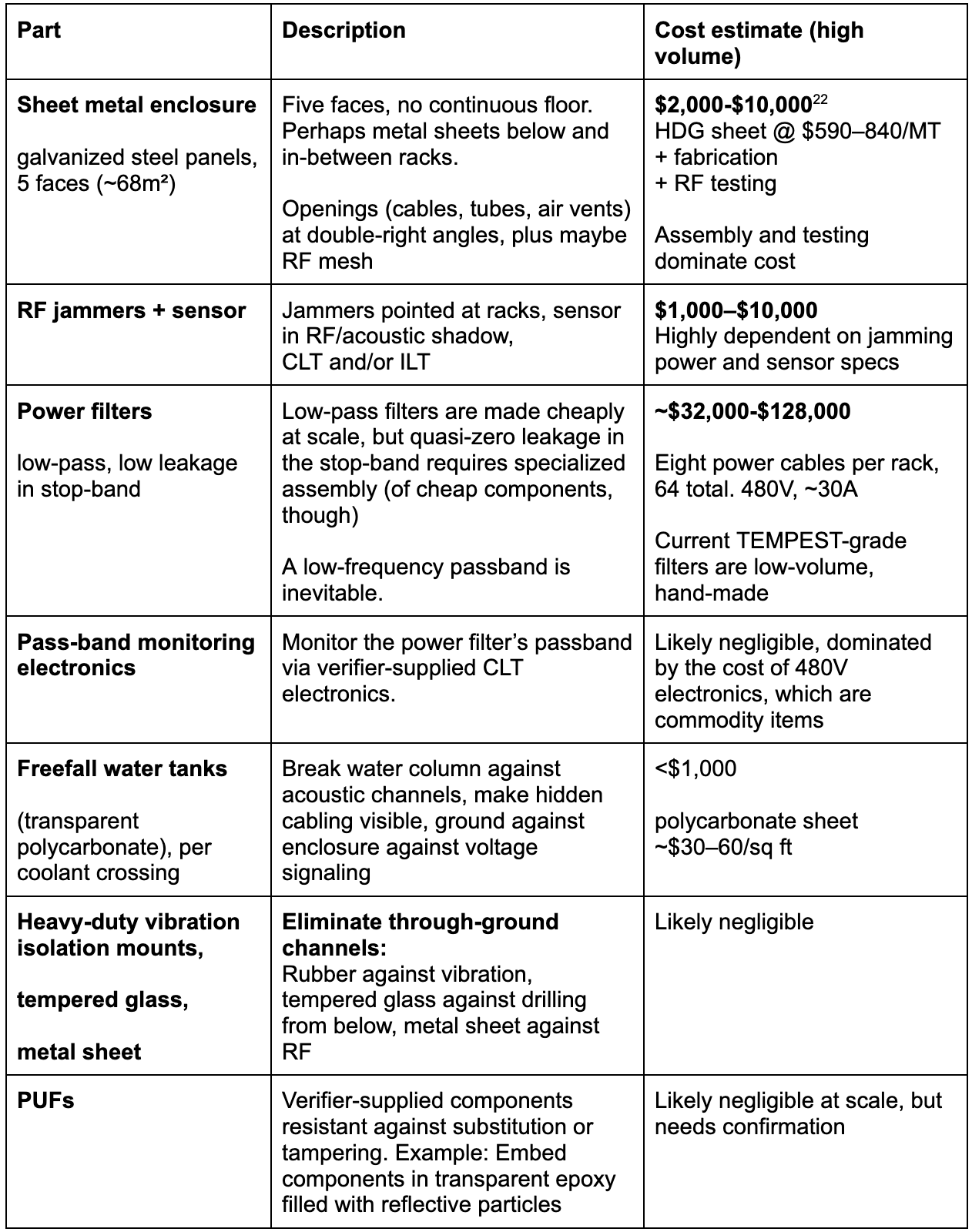
Bottom line: The BOM is likely dominated by power filters and perhaps RF jamming+monitoring electronics. I do not expect the BOM of the enclosure to be the main cost driver, when factoring in the cost of physical guarding and inspection.
Reliably enforcing access controls requires staff around the facility, likely even trained guards. Destructive teardown inspection of racks at a sample size of 10 would disassemble or destroy tens of millions of dollars of hardware each time.
Conclusion
I think there is promise in a multi-layered setup of cheap enclosures, filters, monitors and inspection. Before trusting a design such as the preliminary example setup I proposed above, potential members of an AI agreement will probably want to build and red-team a prototype. There are some remaining uncertainties. For example, I expect the main cost driver of the BOM to be power filters, but pinning down how much exactly mass manufacturing would cost has proven difficult.
In a rushed, time-sensitive scenario, one would first prioritize the side-channels that are high-bandwidth without purposefully hidden, malicious hardware. I expect that the most critical side-channel would be RF emanation from stock components and conducted channels in power lines. As the defender suspects the adversary to go to increasing lengths to evade monitoring, and as manufacturing of components such as power filters ramps up, more defenses can be added incrementally.
I hope this work serves as a starting point for further clarifying the threats of -and defenses against- side-channels evading datacenter workload verification.
Footnotes
- "Security Against Covert Adversaries: Efficient Protocols for Realistic Adversaries," TCC 2007 / Journal of Cryptology 2010.
- Which does not mean practically viable. Real-world devices never perfectly reach the theoretically possible Shannon capacity.
- Of course, the monitoring and verification mechanisms must not compromise any confidential information of the covert adversary. The goal is ensuring that the data is screened for compliance, without leaking beyond the process, authority or machine performing the check.
- TEMPEST & Van Eck Phreaking (NSA / GCHQ): The NSA and allied agencies discovered that the electron beam inside a CRT monitor (and the cables connecting it) emitted electromagnetic radiation. In 1985, researcher Wim van Eck publicly proved what intelligence agencies already knew: you could park a van outside a building, point an antenna at a room, capture these stray radio waves, and reconstruct the target's computer screen on your own TV. The NSA codenamed this entire field of emission security TEMPEST.
"Hearing Math": In 2013, researchers (including Adi Shamir, the "S" in the RSA encryption algorithm) figured out how to steal encryption keys by listening to the acoustic vibrations caused by CPUs running prime factorization. In doing so, the CPU draws power from capacitors, which in turn resonate coils, which emit high-pitched audio.
Visual Microphones: When people speak, the acoustic sound waves cause microscopic vibrations on the surface of objects in the room. In 2020, researchers pointed a telescope at a hanging lightbulb in a room hundreds of meters away. Attached to the telescope was an electro-optical sensor that measured the microscopic fluctuations in the lightbulb's brightness caused by the glass vibrating as people spoke in the room. They successfully recovered a conversation in real-time. By recording a potato chip bag through a window with a camera, other researchers tracked the color shifts of the pixels and reversed the vibrations back into intelligible audio. - When SNR varies with frequency, the general form is C = ∫ log₂(1 + S(f)/N(f)) df, integrated over the frequency band. This reduces to the simplified form when signal and noise power spectral densities are both flat across the band. In the low-SNR regime (SNR ≪ 1), capacity depends only on total signal power divided by noise PSD regardless of frequency distribution, so the simplified form is sufficient for the analysis in this document.
- C = B log₂(1 + S/N). For treated coolant water (σ ≈ 10μS/cm, typical direct-to-chip specification) in a 2m × 1cm² path, column resistance is R = L/(σA) ≈ 20MΩ. Stray capacitance to surrounding grounded metal sets an RC roll off on the order of 100kHz. Johnson noise across R is V_n = √(4kTRB) ≈ 200μV at B = 100kHz. A transmitter injecting 10mV gives SNR ≈ 34dB, yielding C ≈ 1.5Mbps. Higher stray capacitance or water approaching ultra-pure drops bandwidth and capacity. "hundreds of kbps" is the conservative end of the resulting range. Order-of-magnitude estimate, not independently verified.
- Demonstrated Faraday-penetrating magnetic covert channels all operate at low carrier frequencies. ODINI reports 40 bps at 1.5 m through a Faraday cage via CPU-core load modulation, and MAGNETO 5 bps at 12.5 cm through a Faraday bag. Purpose-built through-metal coils reach 100 bps through 1 mm aluminum at 2 kHz. The ceiling is set by skin depth: Guo & Sun (2019) measure the penetrated field through 1 cm copper as essentially flat below 200 Hz and fully extinguished by 100 kHz.
- Such sensors could be placed before signal attenuation, right where the attacker’s signal would originate.
- The H04K3/45 patent class descriptor.
- However, enclosures around AI racks and pods would need to handle high-power airflow, high power cabling and many optical links, all of which would need complex handling to meet such attenuation standards. For this reason, the example defense architecture further below recommends cheaper and multi-angle conduits, combined with honeycomb meshes and look-through jamming to still suppress SNR to the required levels.
- Modern rack-scale servers house enough HBM to fit more than two copies of even the largest frontier transformer models, one for prefill, one for decode. There is a bountiful margin for KV cache even at large batch sizes.
- Strictly speaking, the ratio of prefill and decode is not 1:1 in general.
- This addresses tampering after, not during manufacturing.
- Easier to verify for standardized, portable parts (of servers etc.) than building structure.
- Reference architecture: DGX GB300 SuperPod scalable unit. A DGX GB300 SuperPod scalable unit contains 8 NVL72 compute racks.
- Faraday cages are established science. At 800 MHz (the carrier frequency exploited by BitJabber, the fastest EM covert channel using only stock hardware that I know of), the skin depth of mild steel is roughly 7 micrometers. One millimeter of steel is therefore about 140 skin depths, and each skin depth contributes approximately 9dB of absorption loss. Only at extremely low frequencies (and therefore information channel bandwidth) can magnetic signals penetrate such walls.
- This may also help resolve legal issues around jamming, though we treat this as out-of-scope here.
- Estimating the cost of such filters produced at volume turned out difficult, as existing products are made mostly made-to-order via manual labour. This is the reason why in the BOM cost estimate below, my estimate range is so wide. The lower end is informed by a deconstruction of all cost-driving components in such a filter, plus a 2x margin for assembly and testing.
- C = B × log₂(1 + SNR). At B = 10kHz and 0dB (SNR=1): 10,000 × 1 = 10,000 bps. At 20dB (SNR=100): 10,000 × 6.66 = 66,582 bps. Per cable. With 64 whips per SU that's 640 kbps to 4.3 Mbps.
- Such transceivers sell at hundreds of dollars each.
- The air-steel impedance mismatch is roughly 100,000:1, giving approximately -88dB transmission loss through a single metal panel (air-coupled ultrasonic NDT measurements confirm ~99.99% energy loss at air/metal interfaces), and each right-angle turn in a cable penetration or baffle adds 15-25dB of diffraction loss at ultrasonic wavelengths (sub-centimeter), following standard Maekawa barrier attenuation.
- At $590–840/MT and ~7.85kg/m² for 1 mm sheet, 68 m² of panels weighs ~534kg (~0.53MT), putting raw material cost at roughly $310–445 for the entire enclosure skin. Fabrication dominates, not material.
- BitJabber (Zhan et al., HOST 2020) achieves 300,000bps at point-blank range using 3-bit M-FSK modulation of DRAM clock EM emissions, with <1% BER. Through a 15 cm concrete wall, it still achieves 100,000bps (B-FSK, <0.5% BER). Range with a standard desktop metal PC case is ~3 meters; with tempered glass, >8 meters. Carrier frequencies tested are 800MHz (DDR3-1600) and 667MHz (DDR3-1333).